| GG Power Unit |
| All photographs on this page are by kind permission of Herr Bernd Dreyer- Germany Alle Fotographien auf dieser Seite sind durch freundliche Erlaubnis des Herr Bernd Dreyer -Deutschland |
Thumbnail panels:
|
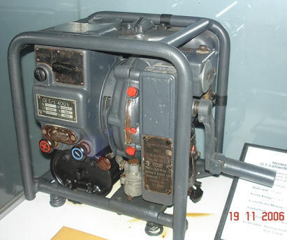

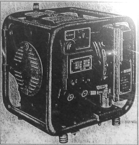


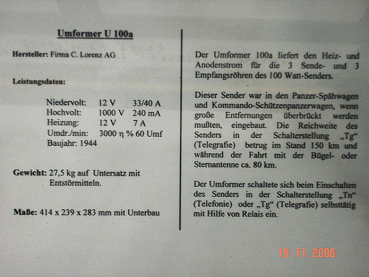
Weight 9.3 Kg Dimensions These generators were used in Command Tiger Tank I and II, the Panther and armoured carriers providing power for driving and radio batteries. The generator engine could be started with push button on “Dyna- start”, or in emergency with the crank starter. ------------------------------------------------------------------------------------------------------------------------------------------- Transformer 100a Transformer 100a, supplies filament and anode current for 3 transmitter and 3 receiver valves for the 100 Watt transmitter. This transmitter was fitted into the armoured reconnaissance vehicles and command armoured personnel carriers. Range of the transmitter in the switching position “Tg“ (Telegraphy) while stationary was 150 km and while in motion, with the frame or star antenna, approximately 80 km. The transformer switched itself on automatically by relays, when turning on transmitters with a switch to position “Tn “(Telephony) or „Tg” (Telegraphy). |
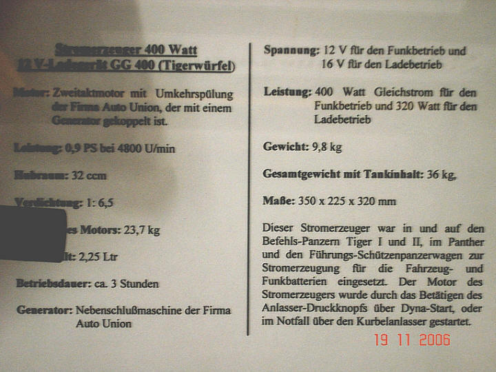
| Translated Museum description |
 |
 |
Extract from D656/22 7 Power supply |
The power supply for radio equipment is supplied by the main batteries via power converters and transformers. The accumulators are connected through the main switch NPA line 2X 10 mm² to the junction box Z 23. The junction box contains safety devices for the different electric circuits and is fitted on tie bar, behind the radio operator. When stationary, the installed GG 400 protects the main drive accumulators. This machine is fitted in the rear right recess. The exhaust from the unit is provided by a pipe connected to the hull roof. Above the set, is a switchbox connected by NPA cable 2X10 mm², to the accumulators' main switch. The switchbox contains a safety device that allows turning off the GG 400 from the electrical system. The transformers are firmly mounted to base plates. The radio operator 1has the transmission transformer U 30 and/or U 20, the base plate U 20 and for the receiver’s transformer EUa the base plate EUa. The base plate U 20 is in the recess to the right of radio operator1. 12 V power supply for the turret intercom, comes through a slipring transducer 8 tlg., Ausf.E, from the hull main accumulators. The NPN cable 2X10mm² (Box Z23) and two cables from 6X0.5 mm² (intercom boxes), are connected to the slipring transducer’s stator. GG 400 equipment is tightly fitted and stored in the hull’s rear right recess. Connection is made with rubber cables to the electrical system from the switchbox (pay attention to correct polarity). The exhaust pipe from the set is firmly attached to the vehicle (tightening nuts firmly, provides full fumes exhaust.) When using the GG 400, unscrew and removed the exhaust external cover cap for the outlet exhaust housing, |
 |