| Tfz 9b Gunsight |
| Function and special characteristics: | |||
The TZF 9 b is a folding binocular, with protective armour-plates at the front of each telescope. Binoculars are designed for long periods of fatigue free observation and aiming. 1. Construction 1 telescope head, shared by both telescopes. Twin housing holds together connecting viewing tubes. This housing is fitted with adjusting lever, designed as clamping device, and also holds a supporting rod for head restraint. Telescope connector contains the telescope head assembly, allowing viewing pieces panning in perpendicular motion of + 30° and - 20°. Both telescopes have illuminated graticules. This unit is plugged into a roof mounted socket, which is operated by a switch located on gunner's left side. Light intensity shutter control lever is located on the left side of the telescope head. Optical data; |
|||
| Magnification x 2.5 TZF 9 b Field of view Line of vision Exit Pupil diameter Overall length Overall width |
TZF 9 b 25° 436m to 1000m distance 6 mm 83.0 cm 28.6 cm |
||
The TZF 9 b binocular telescope has interocular adjustment through a 1:1 ratio gearing. Adjustment is made by rotating cranked eyepieces. Setting is secured by locking a knurled knob on the right eyepiece. The left side telescope is preset for battle condition. Right telescope serves both the 8.8 com gun and coaxial MG. Telescopic gun sight is clamped to an adjustable cradle, which is attached to the mantlet on the left side of the gun. The binocular sights are held by a support arm bolted to the turret roof. |
|||
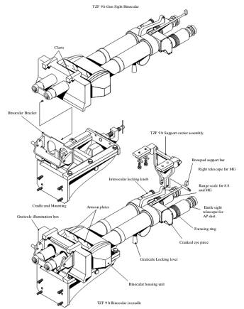 |
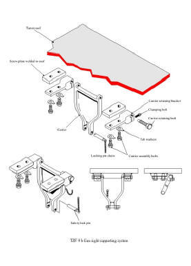 |
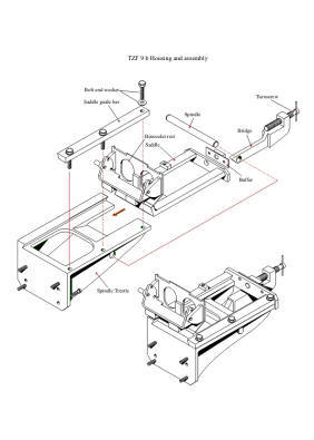 |
|
| Source ; Abbreviated extract from D 565/22 manual and CD Turret manual. |
|||
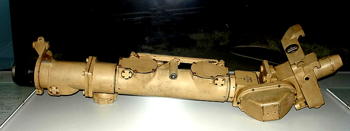 |
|||
| Above TZF 9c for King Tiger at Münster Museum. | |||
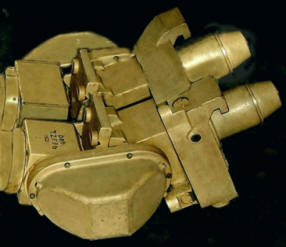 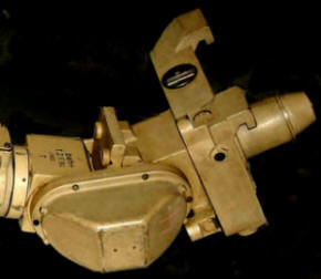 |
| In the telescope head mount, the right and/or telescope is the TZF 9 b. In the TZF 9 C there are two graticule arrangements ; a) Horizontal adjustment b) Vertical adjustment |
Turmzielfernrohr
(TZF 9 b und TZF 9 c) Das TZF 9 b ist ein knickbares Doppelfernrohr, bei dem an der Knickstelle jeden Fernrohres eine Panzerplatte (12) angeordnet ist.Das Doppelfernrohr ermöglich –gegenüber einem einfachen Fernrohr- längeres Beobachten und Zielen, ohne zu ermüden. II Beschreibung Hauptteile des Zielfernrohres sind: Die Einblickstutzen (4) werden durch das Doppellager (5) zusammengehalten. Das Doppellager (5) nimmt den Einstellkopf (11) auf und ist oben als Klemmvorrichtung (7) zur Aufnahme Der Kopfstütze (6) ausgebildet. Die Fernrohrgelenke (3) verbinden die Einblickstutzen (4) mit dem Fernrohrkopf (2) und gestatten Schwenkung der Einblickstutzen in senkrechter Richtung von + 30° und - 20°. 3 Strichplatten (Bild 69 und 70) Im fernrohrkopf des rechten fernrohres beim TZF 9 b bzw. Im TZF 9 c sind zwei Strichplatten angeordnet: a) eine drehbare Die drehbare Strichplatte trägt für das Schießen mit Sprgr einunddreißig kleine Kreise, von denen der erste und folgend jederzweite beziffert ist, für das Schießen mit MG und Pzgr dreizehn kleine Kreise von denen erste und folgend jeder zweite Kreisbeziffert ist. Die verschiebbare Strichtplatte (Abkommenplatte) trägt das Hauptabkommen sowie links und rechts je drei Vorhaltemarken,deren Abstand von einander 4- beträgt. Im fernrohrkopf des linken fernrohres (nur beim TZF 9 b) sitzt noch eine Abkommenplatte 9Bild 68), die durch einen Hebel (18)in das Gesichtsfeld eingeschaltet werden kann. 4. Bildschärfe. Die Bildschärfe wird entsprechend der Sehschärfe (10) eingestellt. Die Einstellung wird in „ Dioptrien“ angezeigt. Quelle; Abgekürzter Extrakt von D 565/22 Grätbeschreibung und Bedienungsanweisung zum Turm CD |